


Share:


Ultrasonic Color Wavefrom Corrsion Thickness Gauge
Brand: PRIDE INSTRUMENT


Ultrasonic Color Wavefrom Corrsion Thickness Gauge
LIVE COLOR WAVEFORM(A-SCAN).
CONTROL OF GAIN, BLANKING, GATE, RANGE, DELAY, RF AND RECTIFY MODES.
DYNAMIC WAVEFORM AND THICKNESS COLOR CHANGE ON ALARM.
If the ordinary thickness gauges are incompetent in the rough applications. Please turn to our TG330, which will maximize measurement performance for challenging applications and provide you with the cost-effective measurement solutions.
PRINCIPLES
The ordinary ultrasonic thickness gauge with the principle pulse/echo method could do the test by the following two conditions.
1. The first underside echo must be higher than the gate. (The height of the electrical level
of the gate is unadjustable)
2. No other noise waves before the first underside echo are higher than the gate.
(Otherwise, we will get the thickness where the noise wave are produced)
For some conditions, the above situations could not be satisfied, for example, the highly corrosive near surface, coarse-grain materials
(e.g. cast iron), aluminum, small diameter pipes, super thin sheet, super thick plate, rough surface, nonuniform inner structure, defect contained workpiece, lamination and so on which could not be tested by the ordinary gauges.
TG330 will solve the above problems easily.
1. Make the first underside wave higher than the gate by adjusting the gain and height of the gate.
2. Invalidate noise waves before the first underside wave by the function of blanking.
Live Color A-Scan
The user could directly see the color waveform of the ultrasonic sound (or A-scan) on the screen, which is quite important for the occasions that we need to check the correctness of the testing results. Many cases will cause wrong testing results or even no readings. We could find the causes easily through the A-scan. Adjust the three parameters of GAIN, BLACKING, GATE, and then we will get the right readings.
The uses for waveform: testing the correctness of thickness readings, finding out the causes of impacting the testing, and adjusting the parameters to solve the problems.
Gain
Adjust the amplification factor of echo signal, increasing and reducing by 1 dB by hand. It is quite effective for acoustic attenuation materials (e.g. cast iron).
BLANKING
Invalidate the waves within the red blanking strip, and omit the useless noise waves that impact the measuring like the waves caused by the rough surface or nonuniform inner structure.
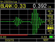
omit the front noise waves by blanking
ADJUSTABLE GATE
The gauge will get the reading only when the wave is higher than the gate. So the adjustable height of gate is very important, especially for the applications of low echo signals (e.g. super thin sheet, super thick plate).
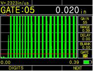
waveform of the 0.02in sheet by PT04
RED ARROWHEAD
A red arrowhead is pointing at the measuring point in A-scan mode, and the thickness value is the horizontal ordinate of this point. It will help to judge the correctness of the reading. We will get the right reading if the red arrowhead is pointing at the advancing front of the first underside echo.
RANGE
Adjust the wave scope on the screen, and they are visually compressed or spreaded. Without the correct wave range, the wave may be out of the screen, but the right reading will still show.
DELAY
Adjust the initial position of the wave on the screen, the wave will be moved visually. Without the correct wave range, the wave may be out of the screen, but the right reading will still show.
The functions of RANGE and DELAY could magnify any section of the wave showing on the screen.
RECTIFICATION MODES
Four modes selectable: RF, Half-Wave Positive, Half-Wave Negative and Full Wave.
RF: describe the whole echo waveform.
Half-Wave Positive: show the Half-Wave Positive without the Half-Wave Negative.
Half-Wave Negative: upturn the Half-Wave Negative and dispose of the Half-Wave Positive.
Full Wave: show both the Half-Wave Positive and upturned Half-Wave Negative.
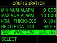
set up rectification modes
ALARM MODE
The high limit and low limit of the Alarm could be set. Dynamic waveform and thickness reading color change on alarm.
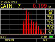
half-wave positive on alarm
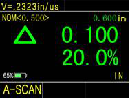
REDUCTION RATE MEASURE
Differential Mode and Reduction Rate Mode are standard Features. Differential Mode shows the thickness variation from a pre-set thickness value. Reduction Rate calculates and displays the percent of thickness reduction after a material thinning process.
MIN./MAX. MODES
On this mode, the current thickness, minimum thickness and the maximum thickness will be shown on the screen at the same time. You could drag the probe along the surface of the work, and the minimum and maximum will be shown automatically on the screen.
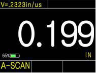
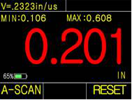
Reading in white means couplant well Differential Mode and Reduction Rate Mode Min./Max.modes, reading in red means alarm.
Inquiry - Ultrasonic Color Wavefrom Corrsion Thickness Gauge


